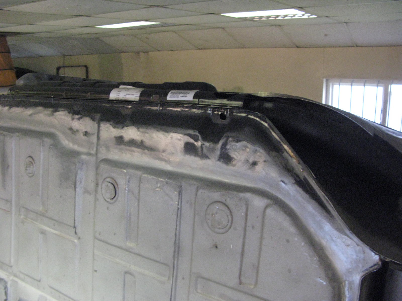
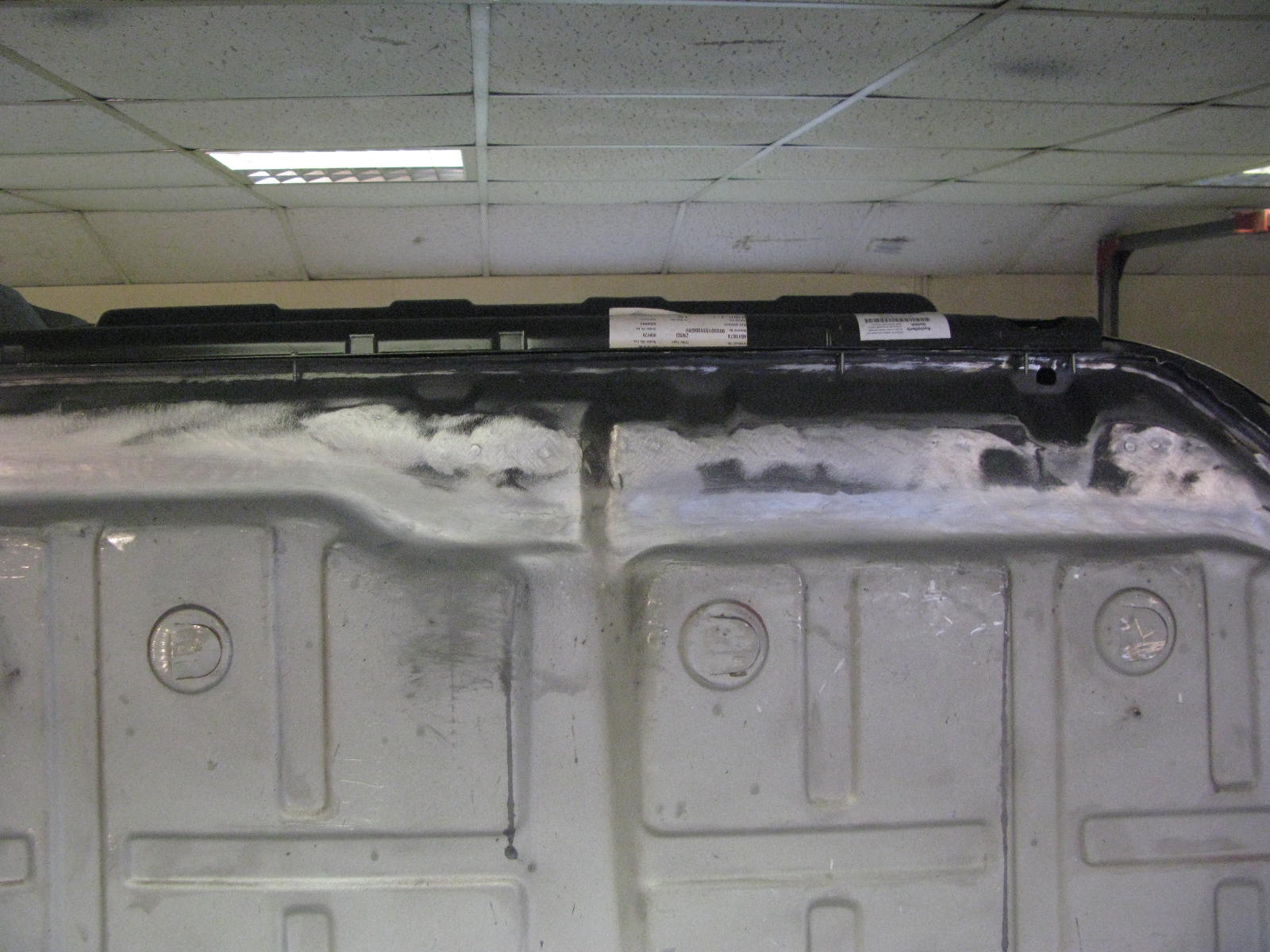
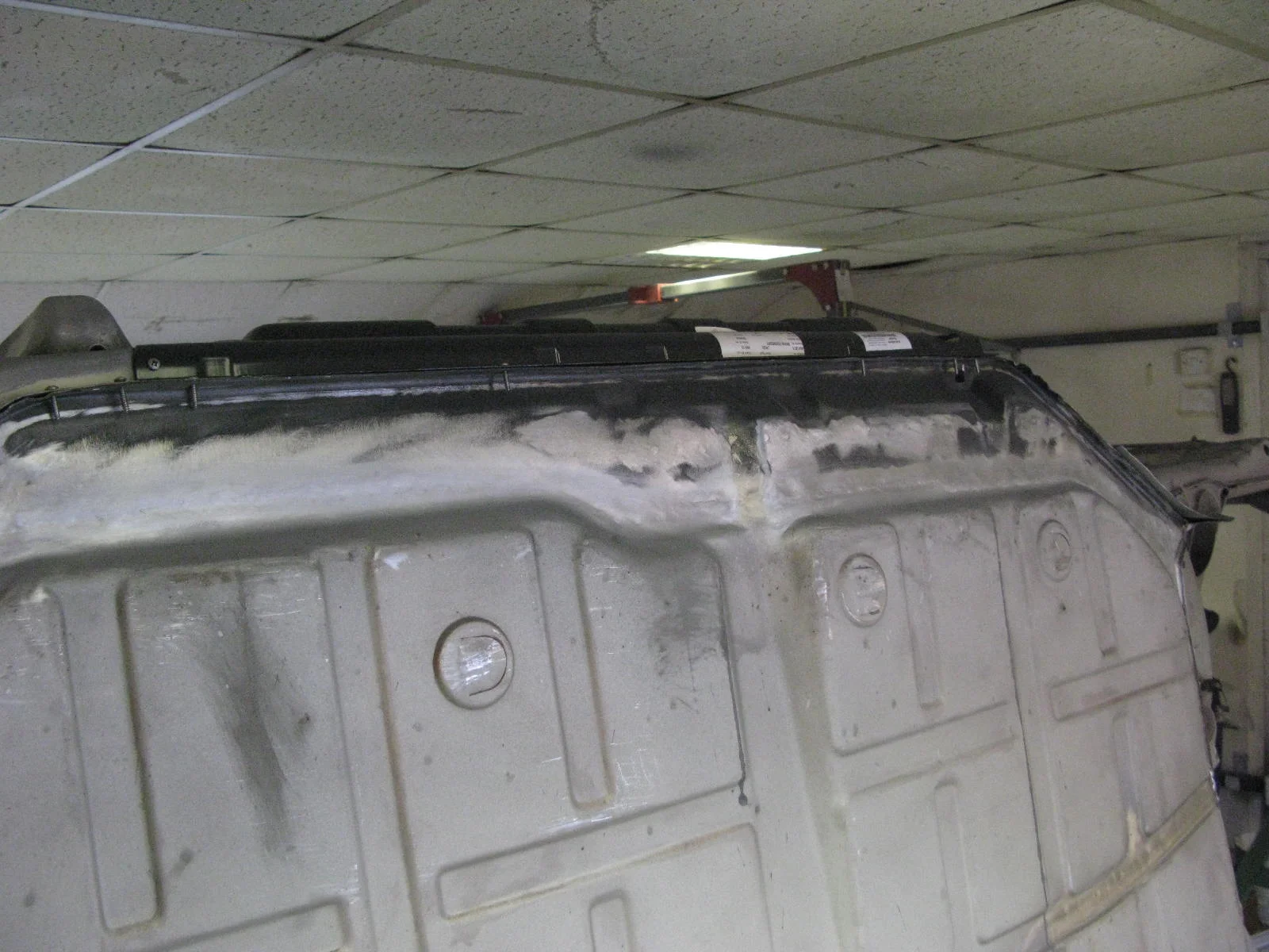
RH Torque Tube Area

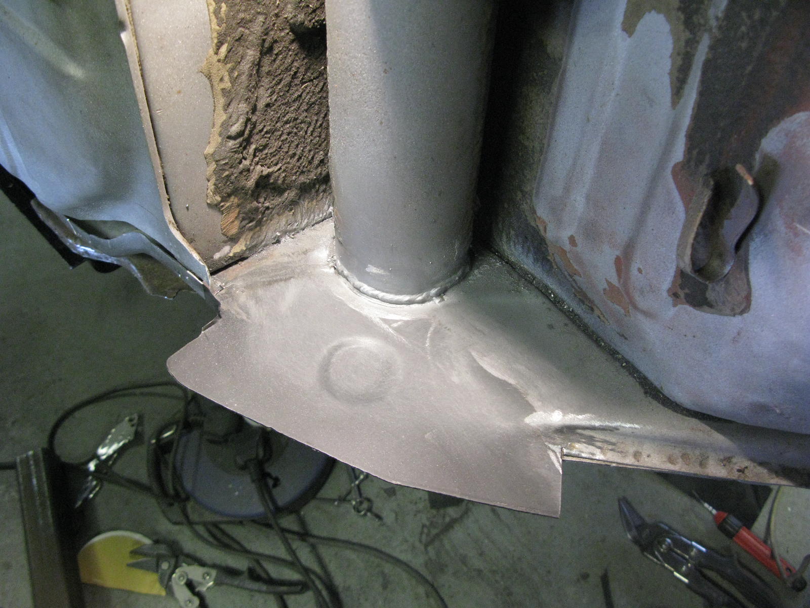
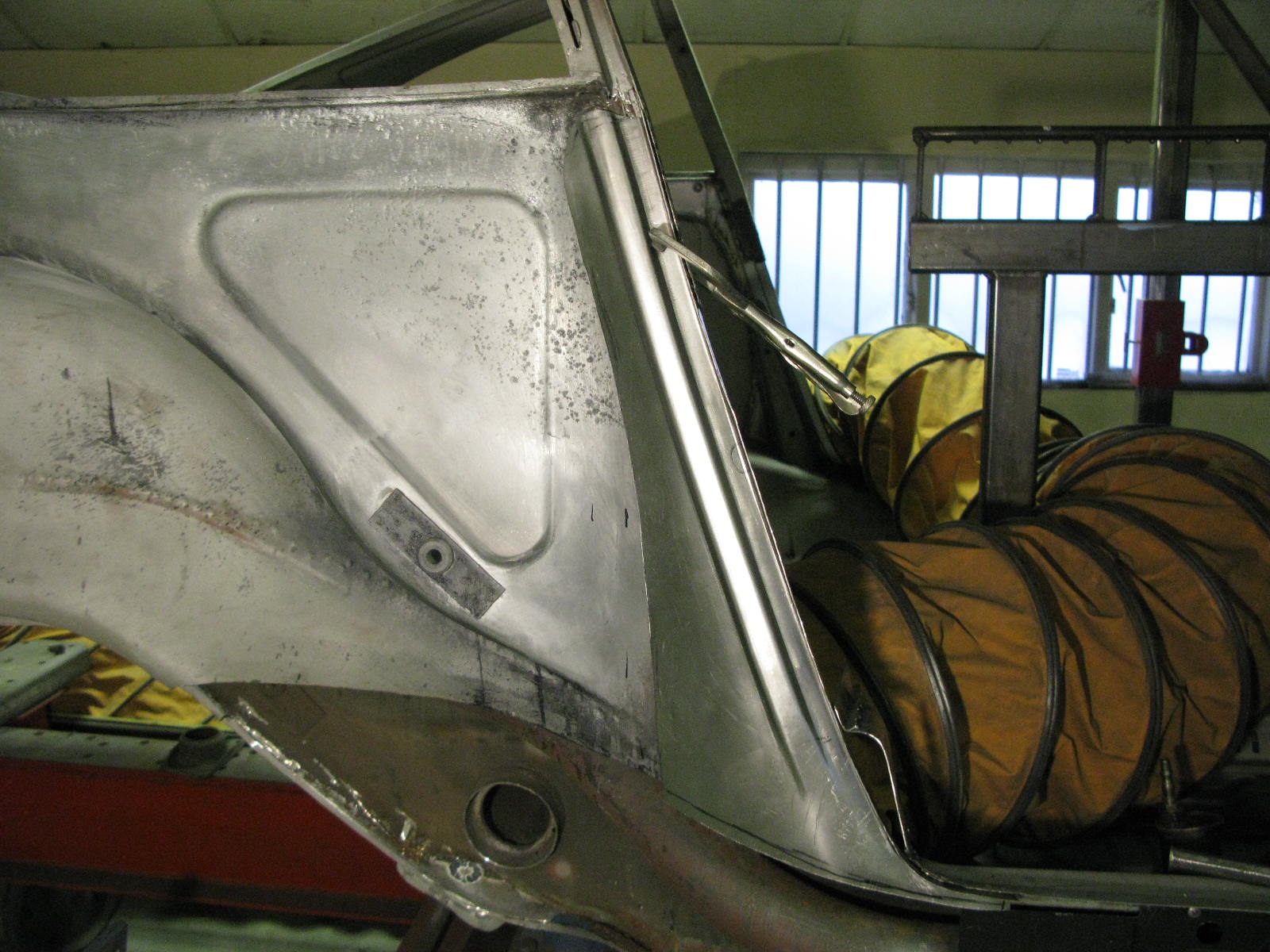
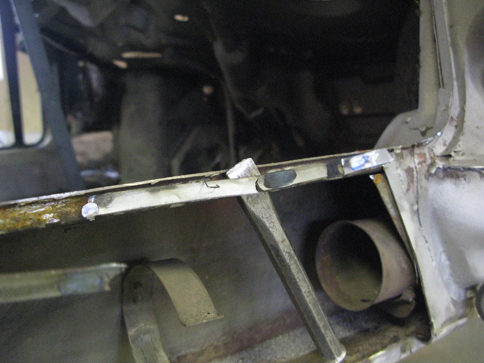
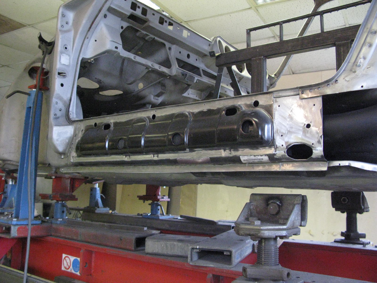
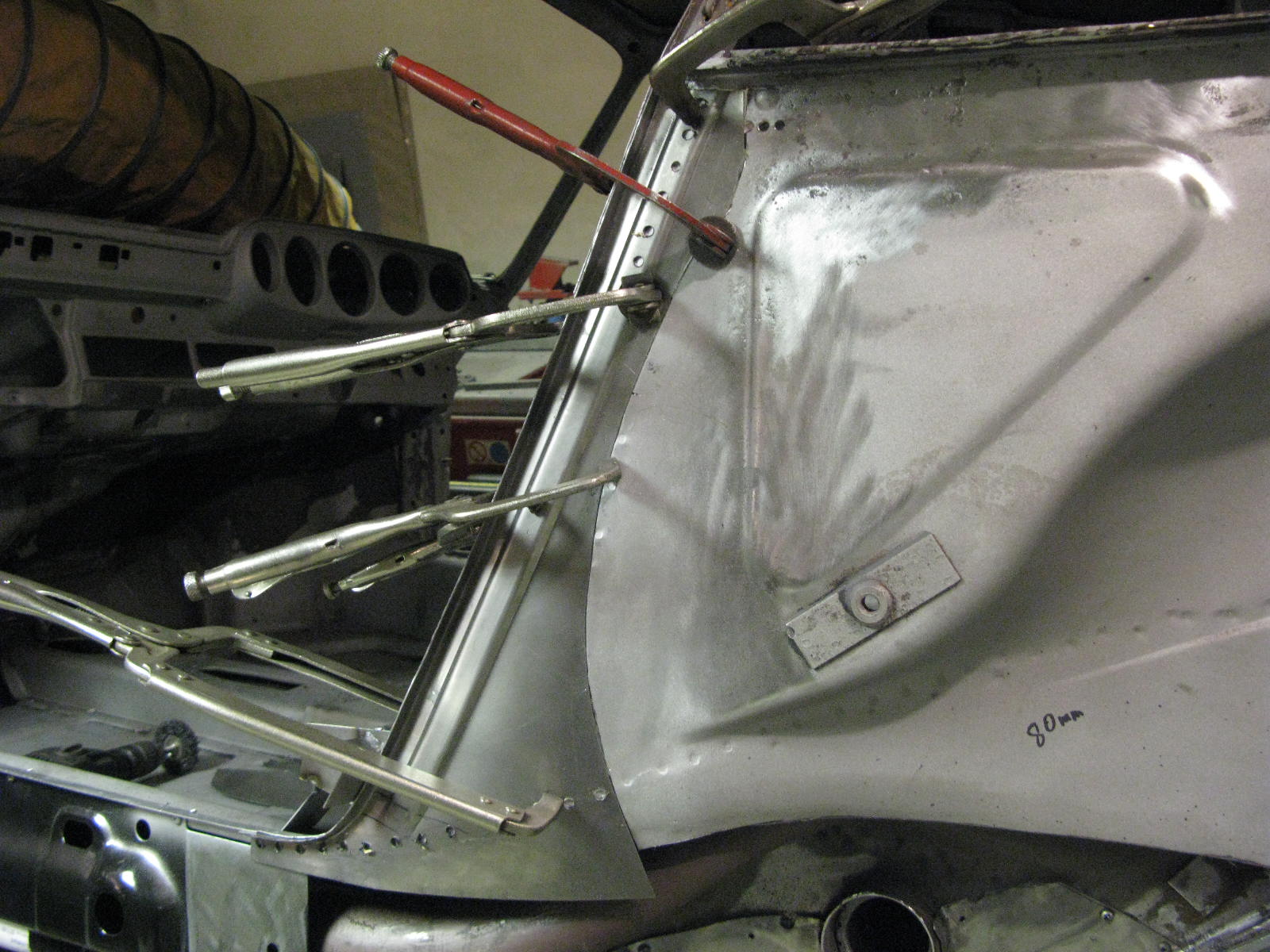
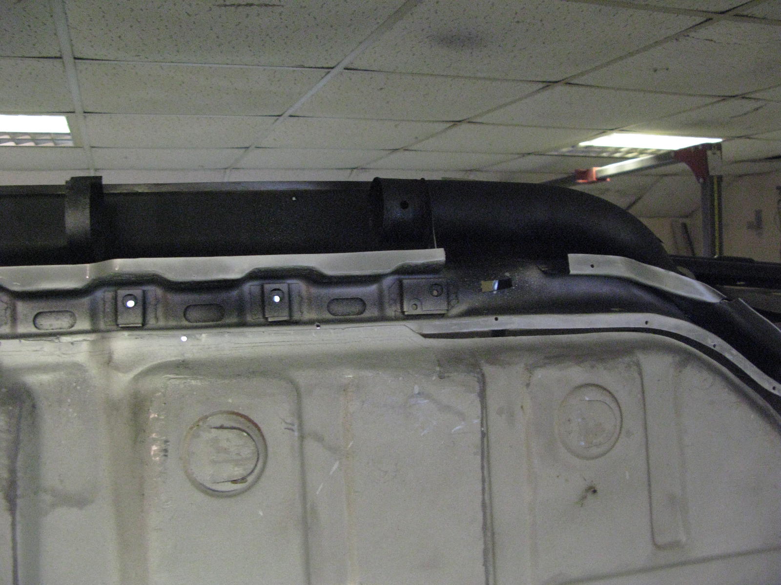
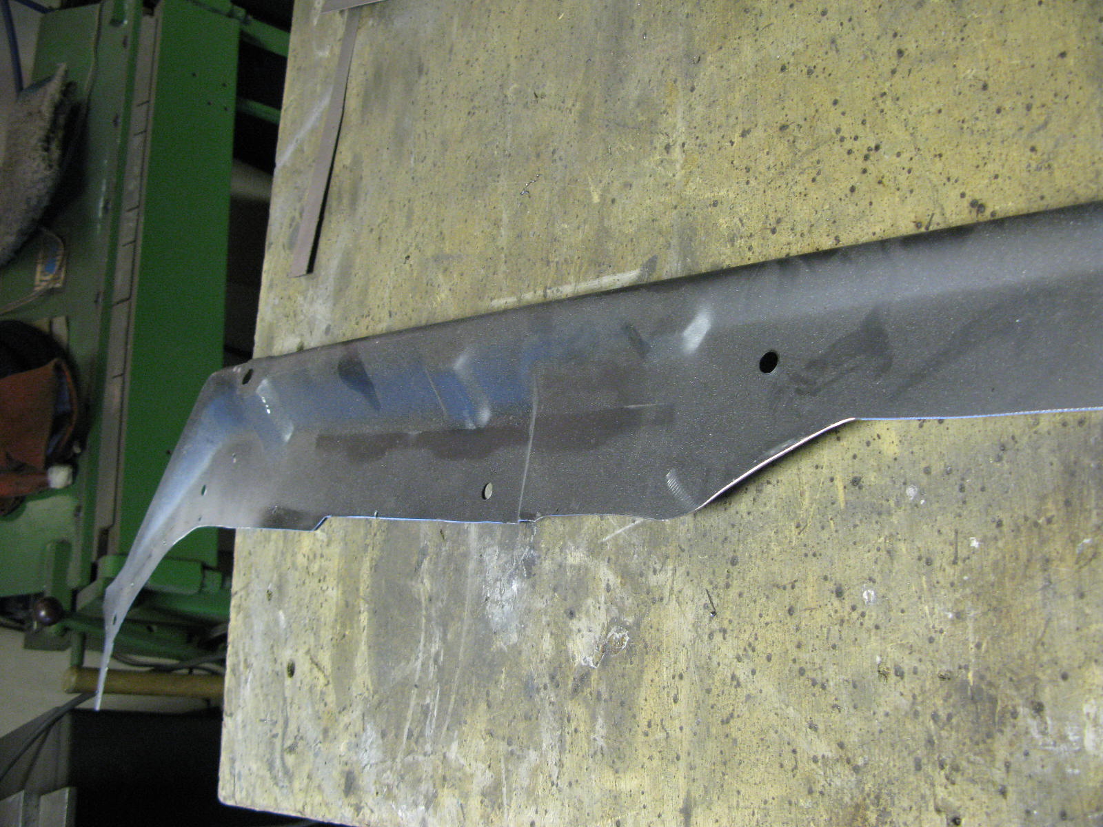
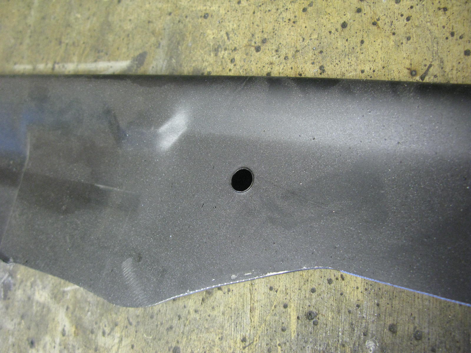
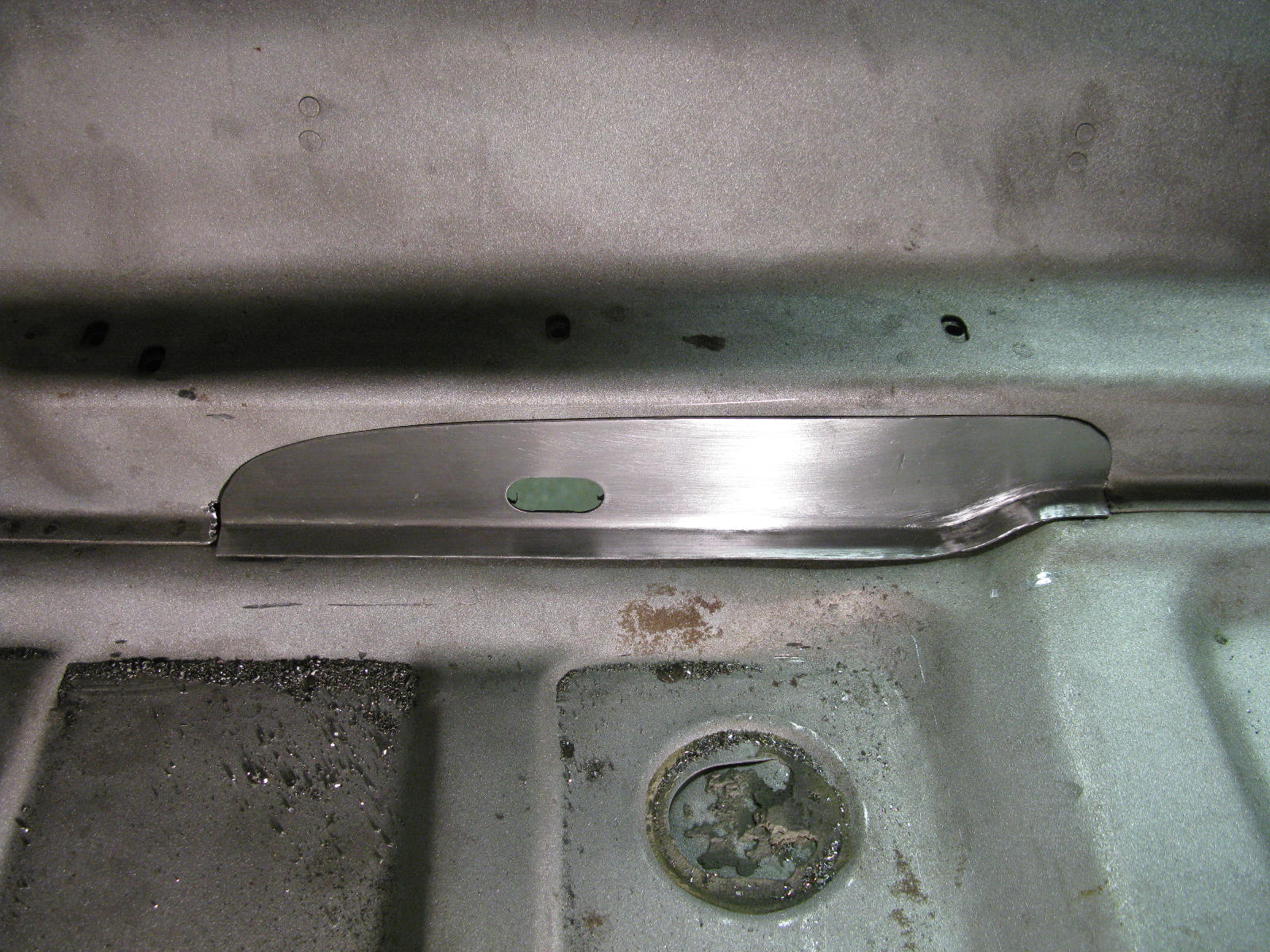
Work begins on the Torque Tube area. First job is correction of a couple of previous repairs.

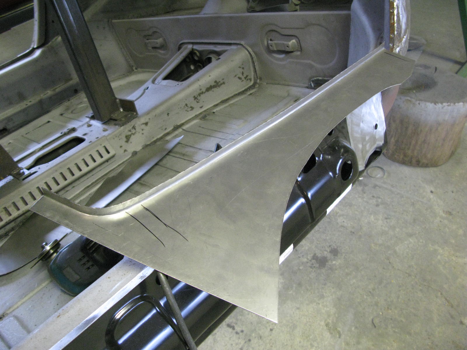
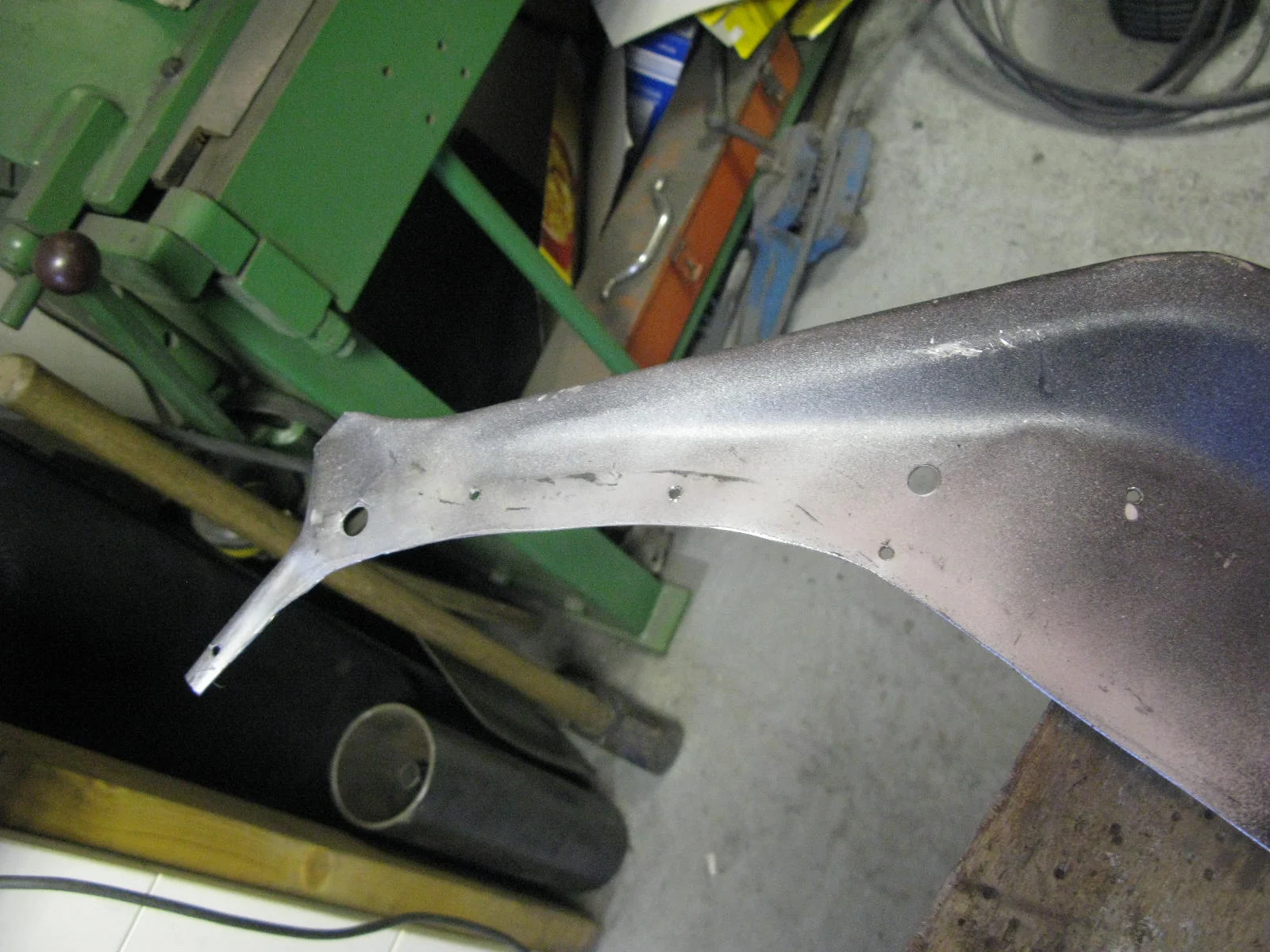
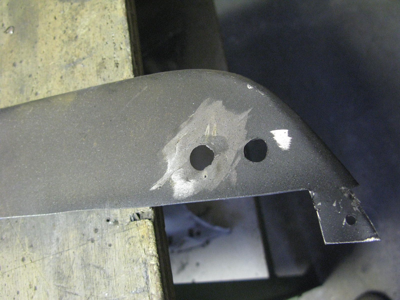
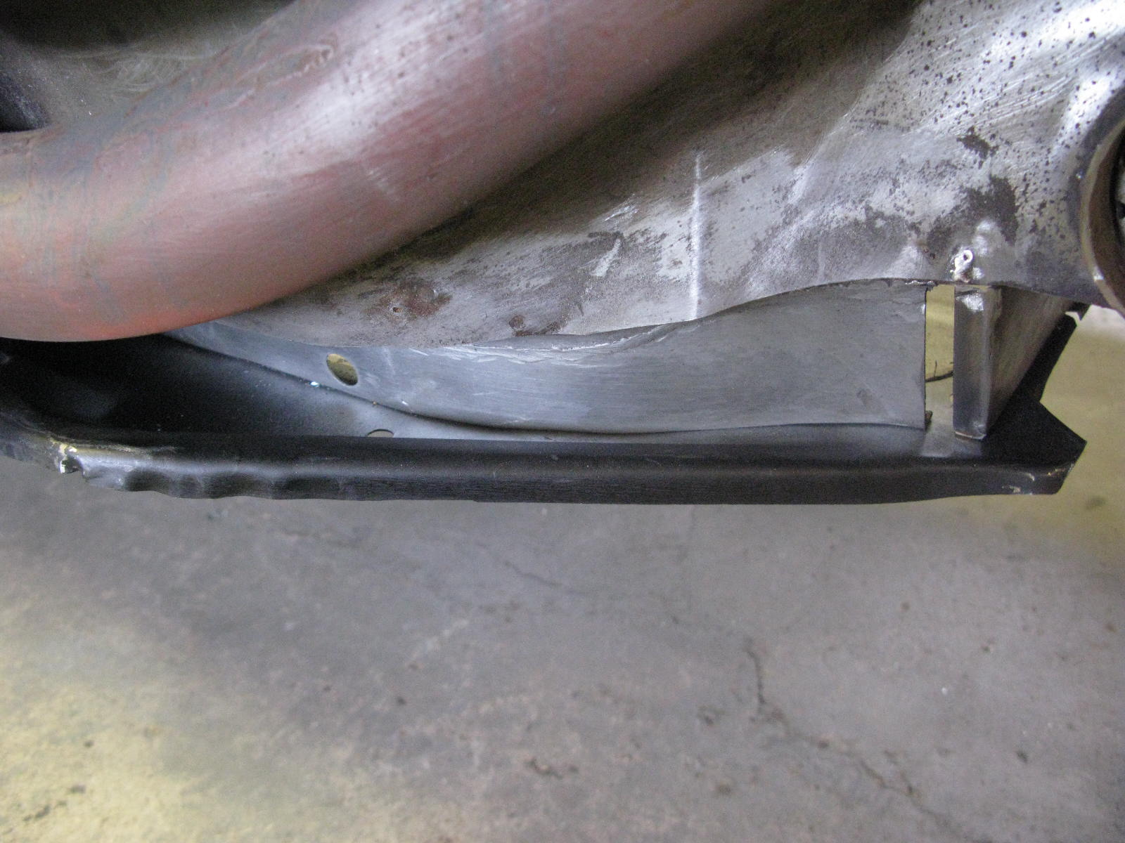
First the intermediate panel, which was left with a big chunk missing at the end of previous work. Lighter, I guess, but not ideal for structural integrity of this area....

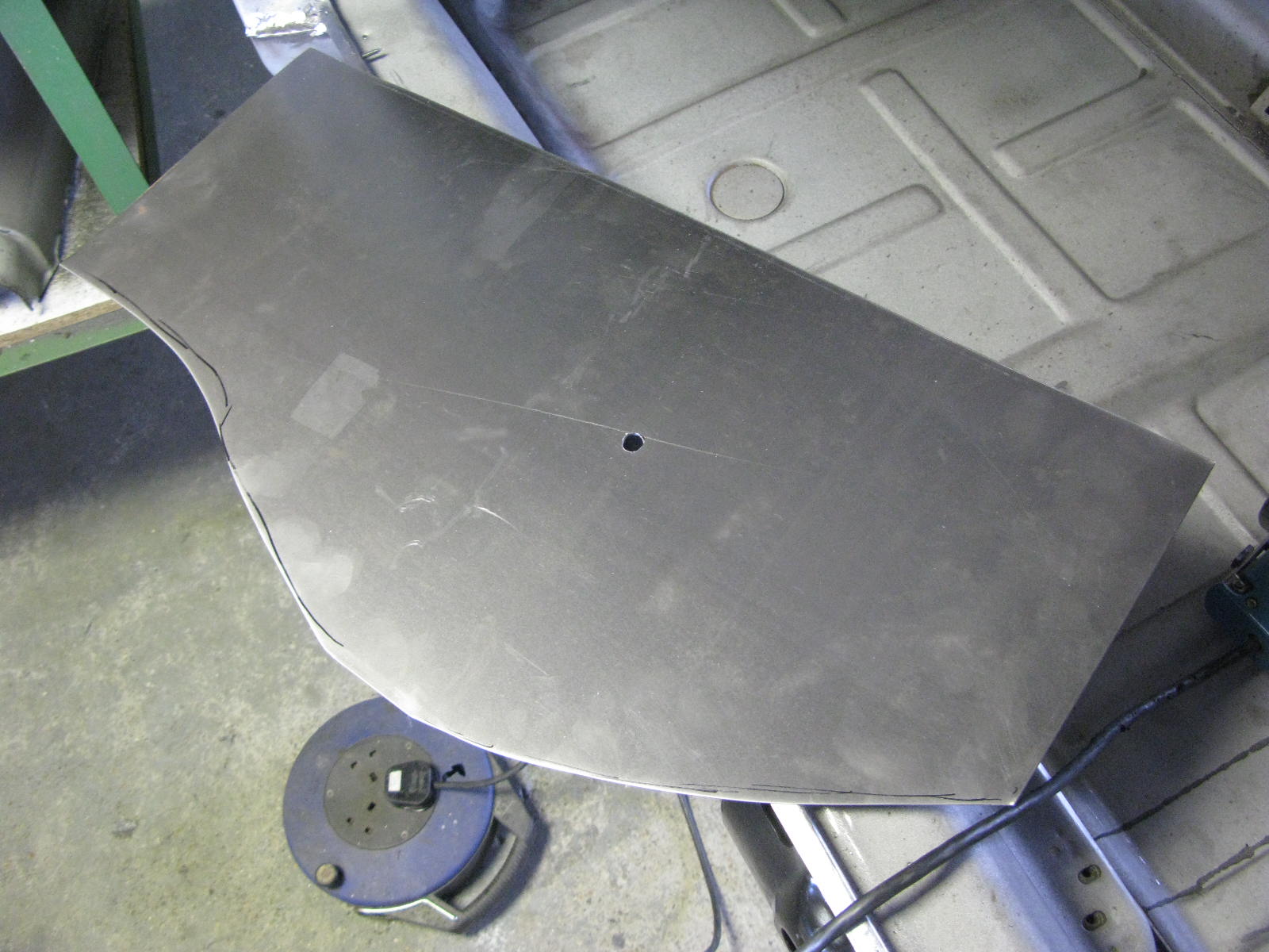
Barry free-handed the repair panel in 18swg as usual. Will be welded in as part of the final assembly of the TT / inner sill area.

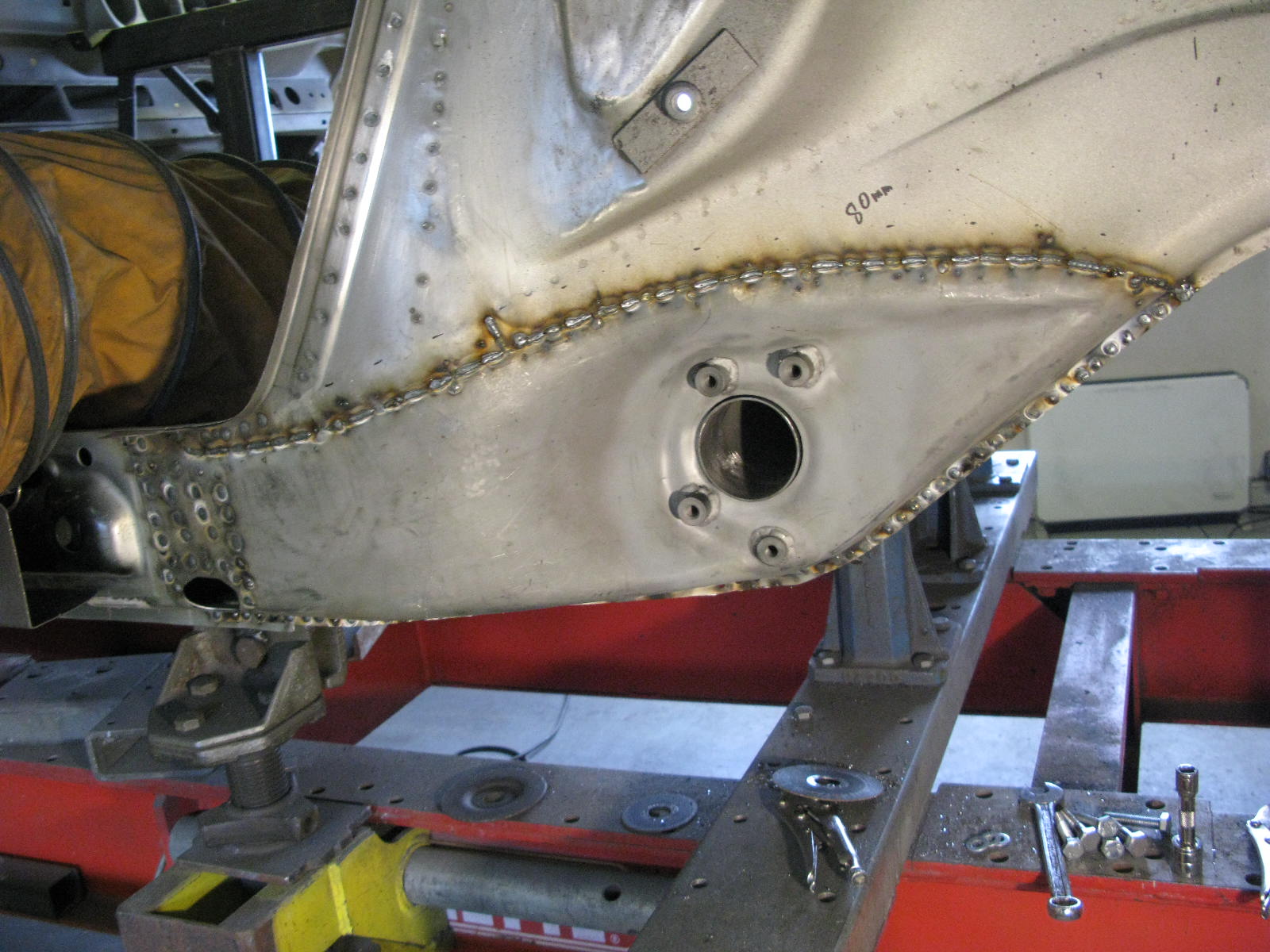
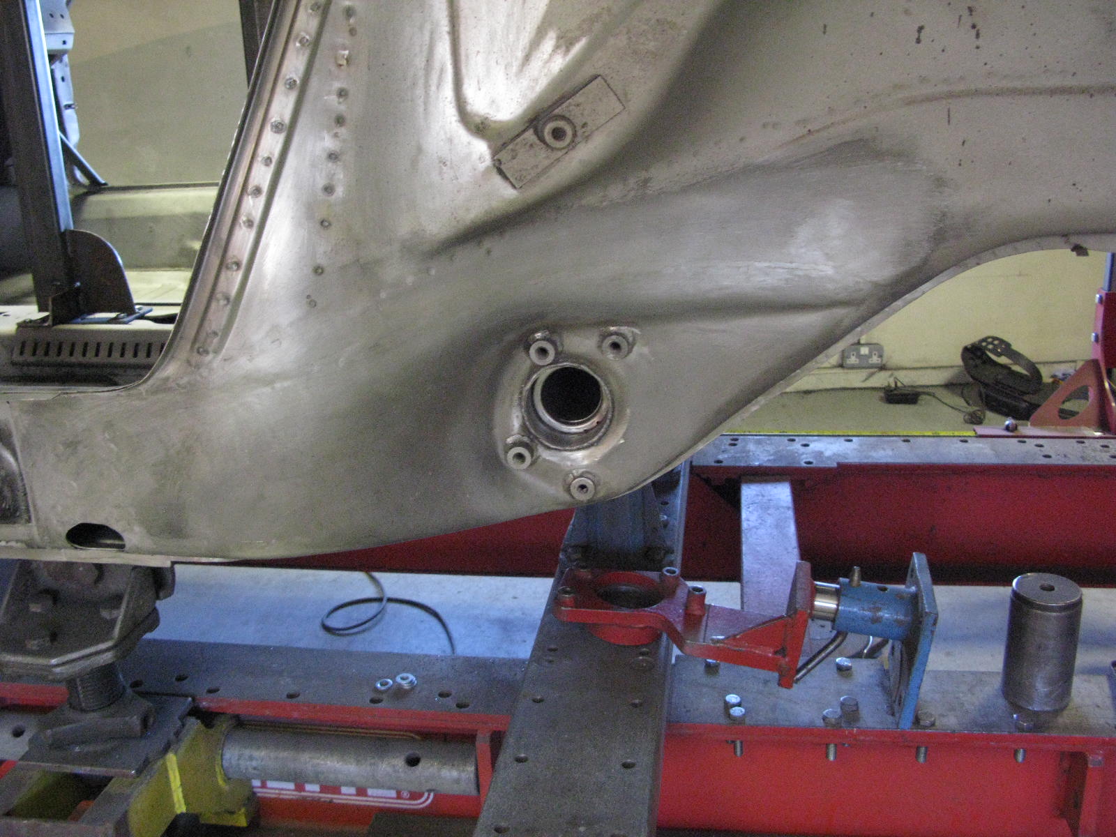
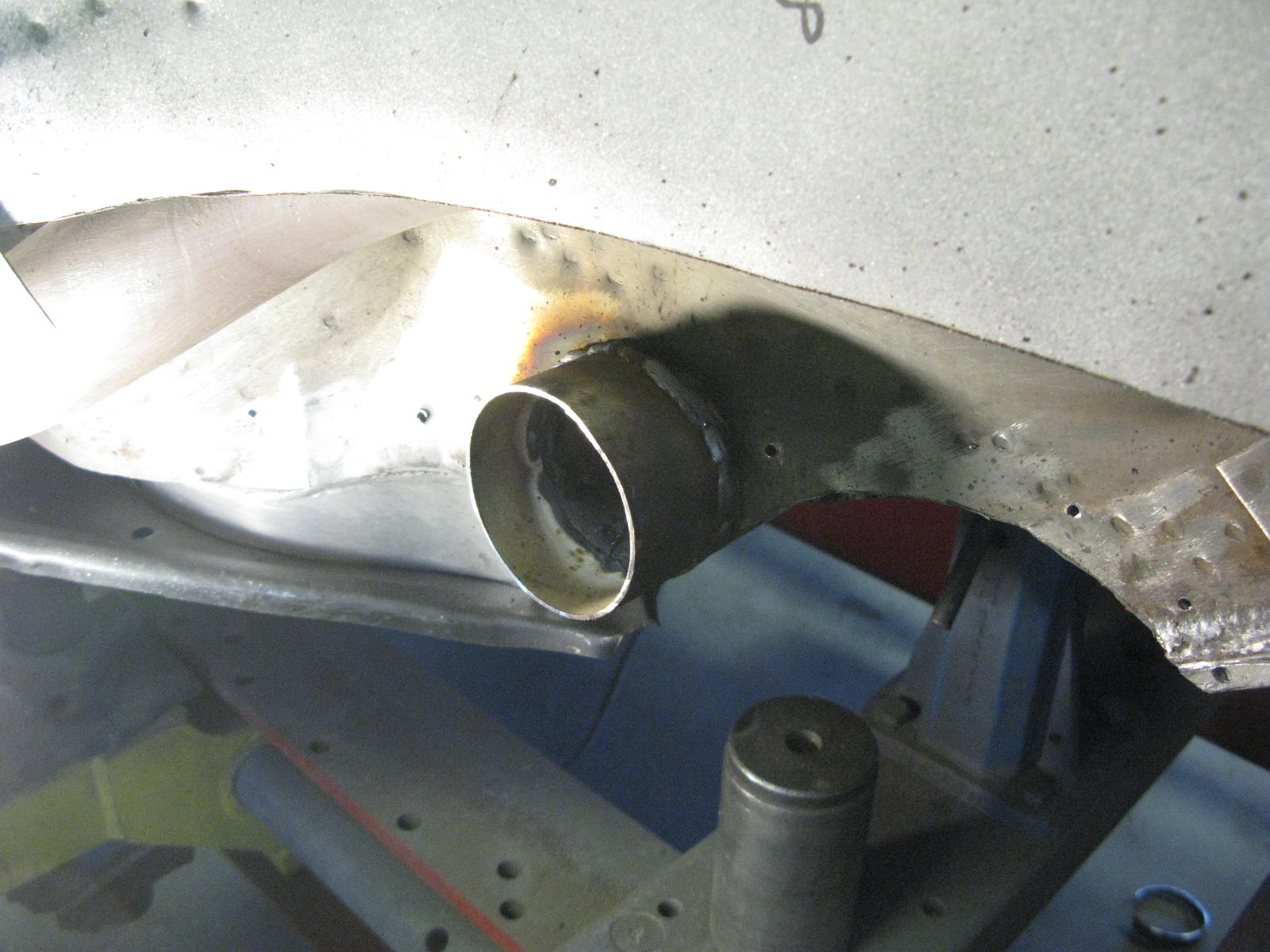
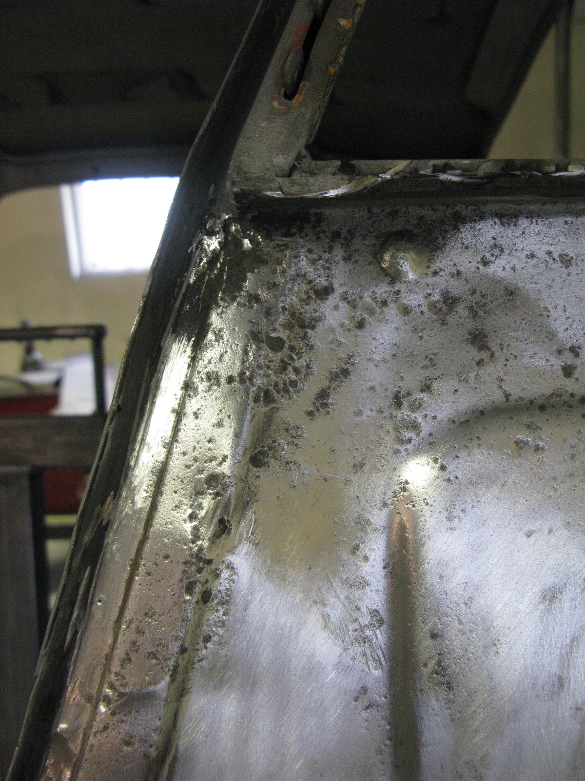
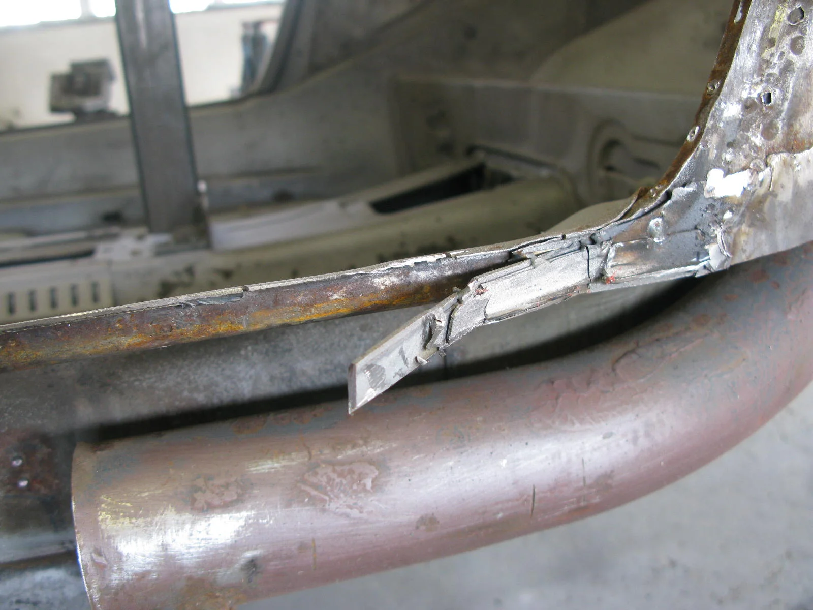
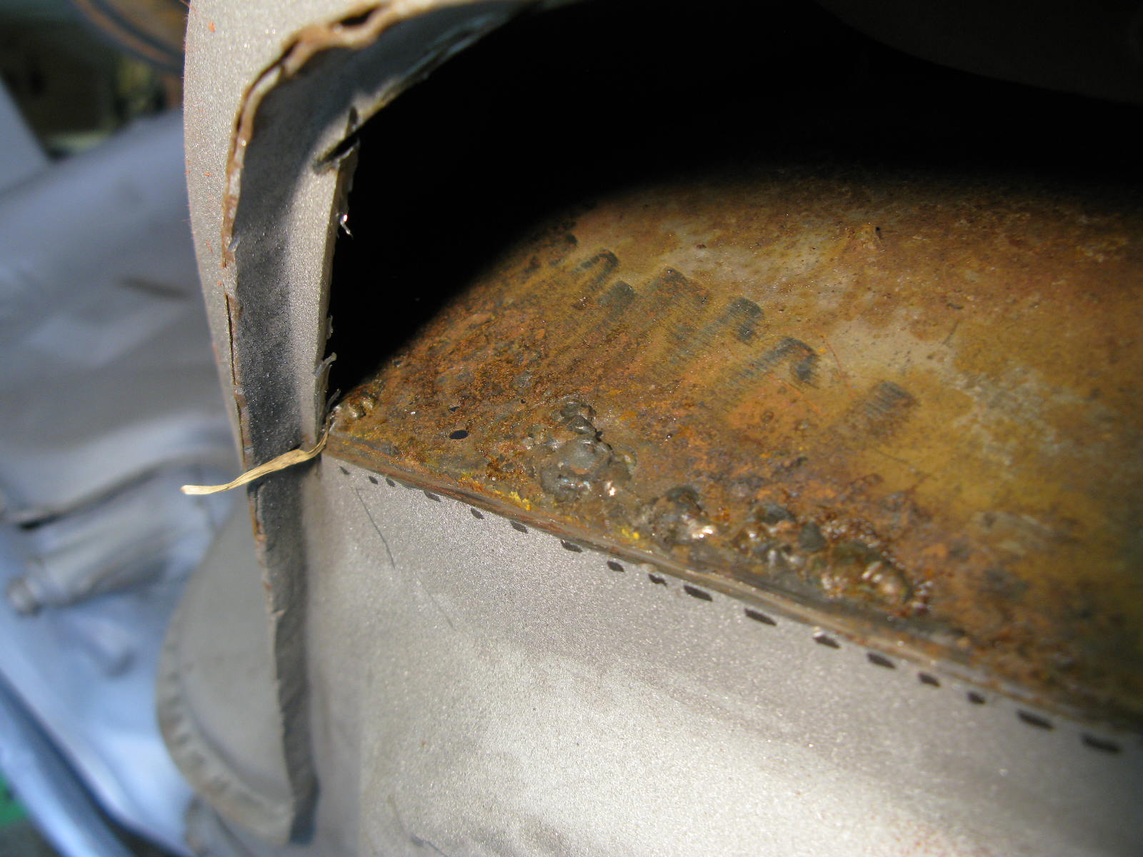
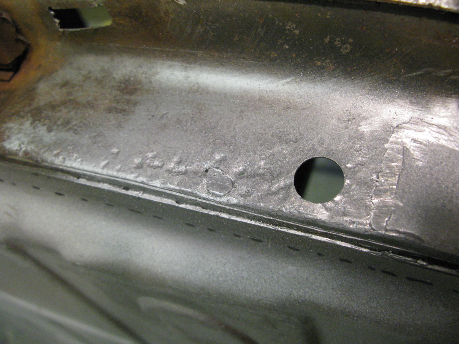
The other correction was to a repair below the torque tube, in the area of the ARB mount.
Doesn't look too bad:

But not so nice from the other side:

So out it comes, replaced by another hand-formed repair piece:

RH Floor Edge

The RH floor edge was scribed in and prepared:

And then, having sanded back and etch-primed the cavity, the floor edge went in for good:

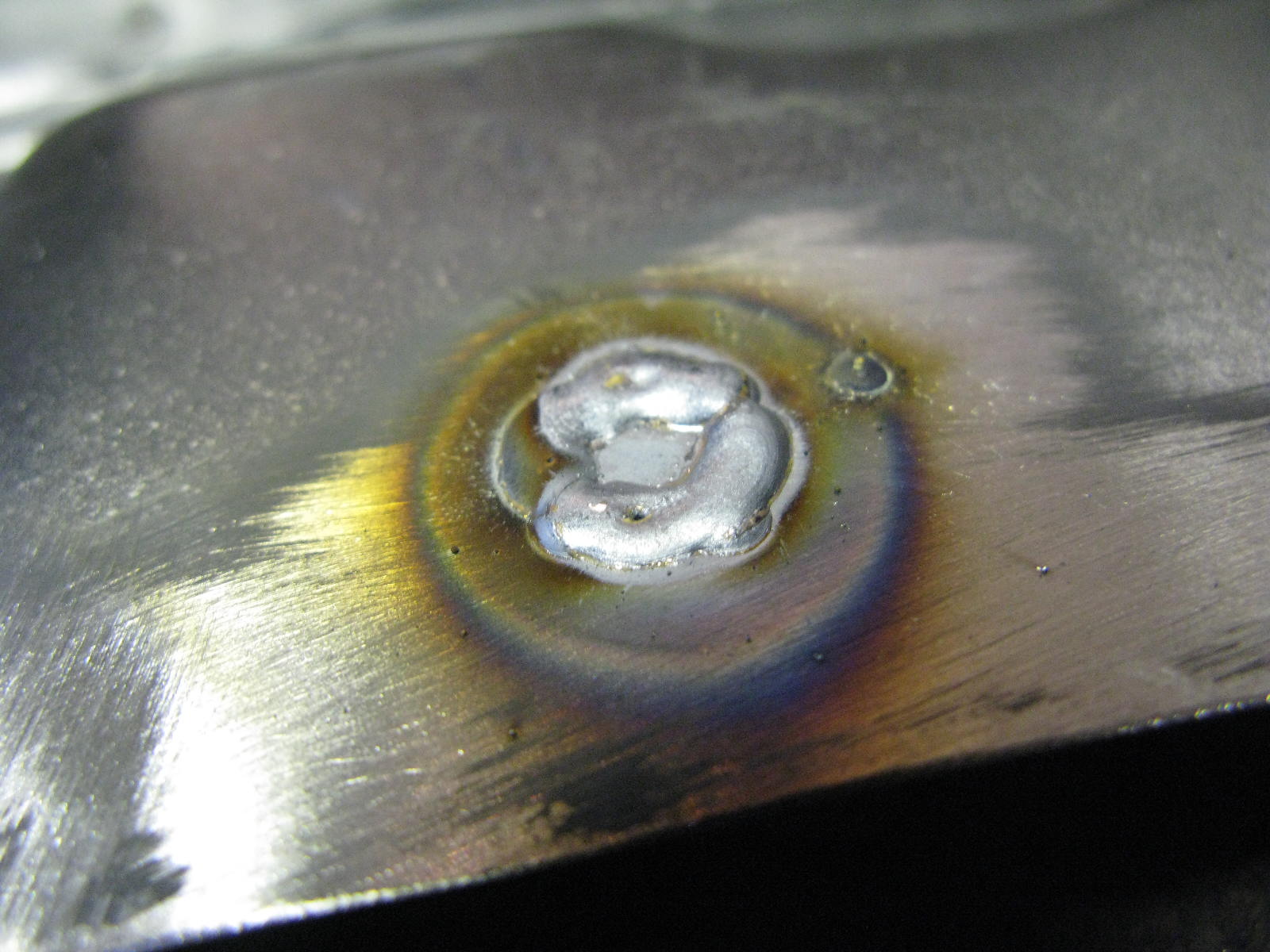
Mmmmm, look at those lovely welds:

RH Floor Edge Small Repair

As I mentioned before, the original floor / tunnel is in good shape. We're only replacing the floor edges. Although I think this approach - keep as much original metal as possible - is right for me and this car, it does eat up time with small repairs.

For example in this small repair there's not much to see from the other side, but now the floor edge is off we can see it's another pitted and holed area that needs to be replaced:

RH Rear Inner Wing: Front Edge

Similar to the other side.

Grotty:

Pullmax wizardry etc, and a fair amount of fettling (it's a tricky shape):

Not Grotty:

RH Seatbelt Mount

The seatbelt mount area on this side had some nasty pitting / small holes:

So the mount came out for blasting and priming, and Barry hammer-formed the replacement section of panel:

You may be thinking - but where does the mount go?
If you put it back in the wrong place, the interior trim will need to be hacked about.

Luckily Barry has thought of this. Did you notice the two small holes in the remaining section of good metal? Here's what they are for:

RH Sill

Making a start on the RH side now, beginning with the sill.

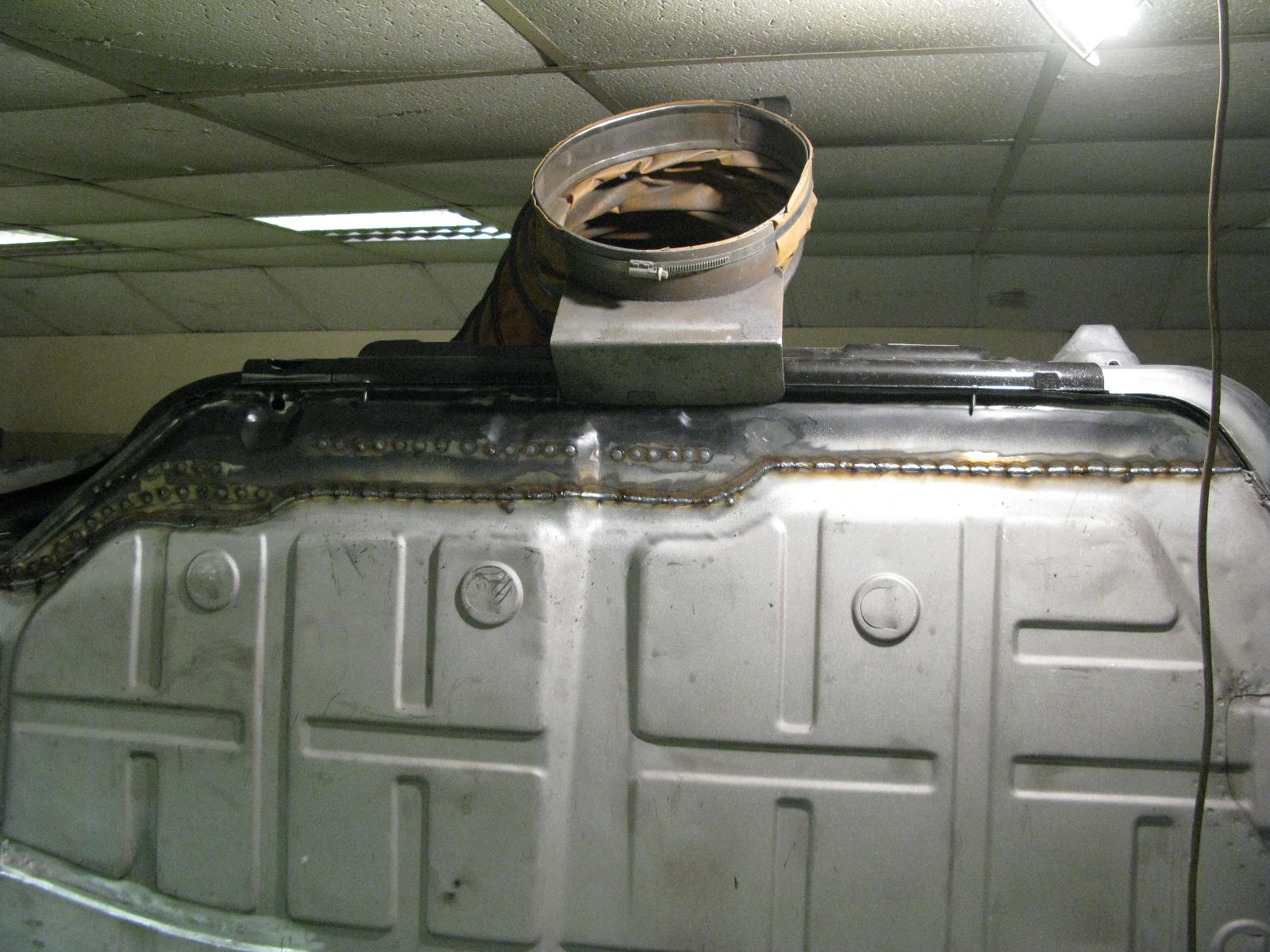
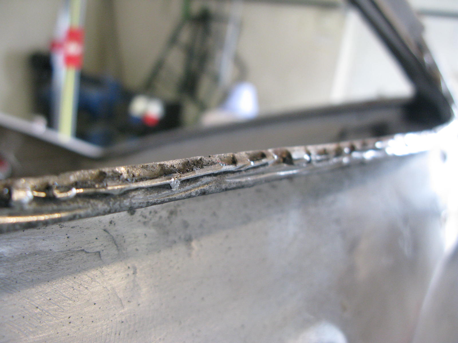
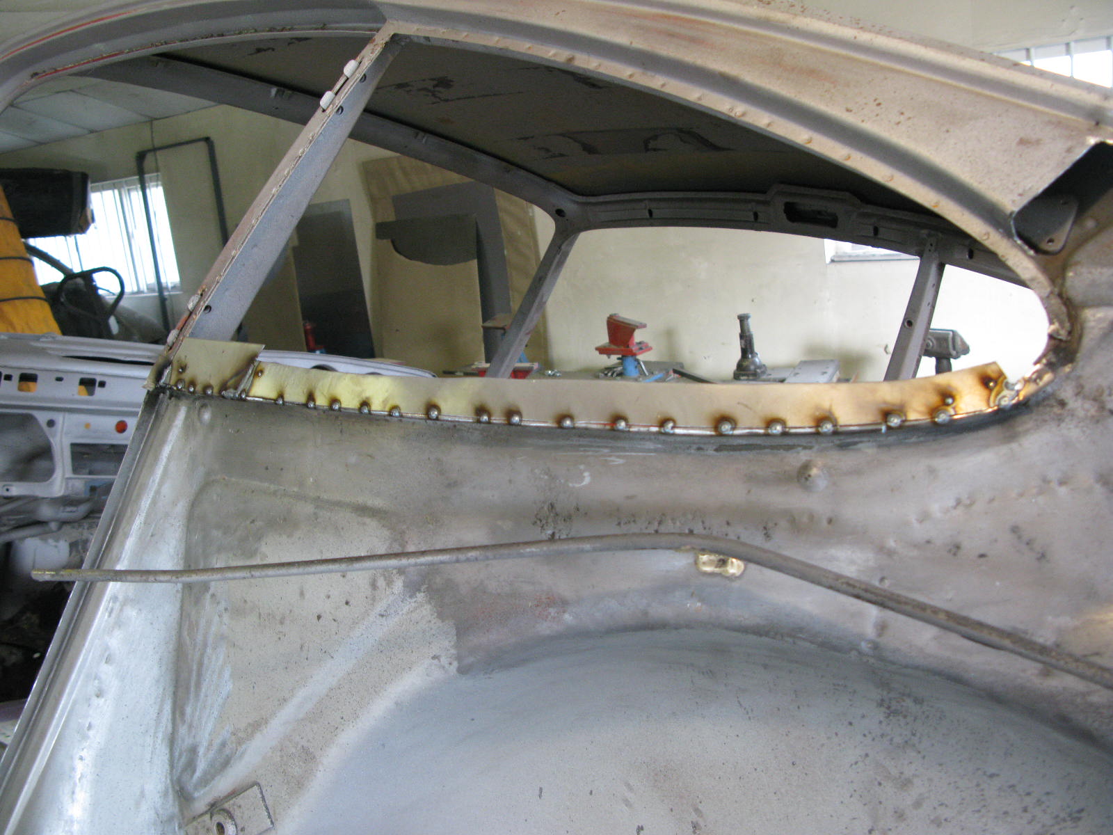
These photos show another example of the previous restoration work - a weld approx every 100mm. Barry tells me one every 20mm is about right. They had also left the freshly-opened seam as bare metal. At least it came off easily!

Barry fabricated a new sill flange to replace the battered old one. Same as the other side.

RH A-Post Base and Nearby

With the A-post base out of the way, the true condition of the inner wing was revealed. Also, some welded holes could be seen a bit further forward, so we elected to replace the whole area.

As Barry says: You can buy this panel, but I have the tooling here, so can make it out of full 18swg, which gives plenty of meat. Frankly most of the time is tweaking the fit to suit a particular car, and this would be the case with either my panel or a bought-in one. This way, I can tweak it as I make it.

End fit has ended up fine, and you can see what those MIG welded pin holes look like from inside. Definitely better off in the bin.

LH Torque Tube Area. Surely it must be finished this time?

Barry rectified the manufacturing error in the Torque Tube repair panel. The jig bracket now fits.

Last job here was the backstop:
If a new end to the torque tube is welded in (as I have done) I usually replace the backstop as well. This means I can tuck the TT join almost out of sight, plus both backstops were poor anyway. I press my own versions, that look stock once installed, but allow them to be welded from inside the tube with a MIG welder.

I'm quite glad to have reached the end of the LH Torque Tube area.

2016 MetalworkRichard Fry
LH Inner Sill

The end of work on the nearside, for now. Inner sill prepped, (new) heater tube in place, welded up and goodnight.

2016 MetalworkRichard Fry
LH Torque Tube Area - Problems

As the previous posts show, the big hole in the middle is perfectly aligned with the jig, and lines up fine with the rear arm retainer (into which the spring plate rubber bush will eventually locate).

But there is a problem. The 4 threaded holes for the spring plate retainer bolts are in the wrong place (per the jig). About 4mm out in rotation.

It's a manufacturing error in the resto panel. Barry says:

the Restoration Design panel for this area (sadly) comes pre-welded. The 'studs' fit a torque tube cover just fine, and with a cover bolted on, the cover and tube look pretty well aligned. As you can see though, the studs are off relative to the jig by about 4mm rotation. I can rectify this by grinding out all of the factory welds, filing out the mounting holes, and then re-welding everything together. Frankly it's a PITA job which will take about 2-3 hours per side.

I'm happy to rework these, or we can choose to say the cover and tube align O.K., they are rubber bushes with a bit of give, let's live with it.

I think my advice would be that if you are retaining rubber bushes, we leave alone (the current position won't affect suspension travel). If, on the other hand, you are going for any solid type bushing / bearing, then I think we'd better bite the bullet and re-work the area. BTW, there's no way that this is down to the position of the actual panel on the car, everything else fits just so, including where it meets the actual tube.

I decided to re-do them. A PITA job that takes 2-3 hours per side. Sorry Barry. Buyer beware on the Restoration Design panels... Although in fairness the Porsche ones are far from perfect. Both are ambitiously priced, and I'm not especially impressed by the quality:value ratio.

2016 MetalworkRichard Fry
LH Torque Tube Area

There are various ways to repair the torque tube itself. Barry felt that, in this particular case, the best approach was pretty clear:

With access as good as it'll ever be, the end of the old torque tube was removed, and a replacement piece welded on. As mentioned before, as the rest of the tube is perfect, as it the surrounding metal, a butt weld is perfectly fine here (not to mention pragmatic). The sleeved type repairs definitely have their place, but not needed this time. Later on I'll make you a new torque tube backstop and weld that in. As can be seen, the jig bracket moves very freely.

So far so good...

2016 MetalworkRichard Fry
LH Torque Tube Area

Over to Barry:

Various puzzles are now solved as folows: We need the floor in to give the point at which to aim the new inner member base around the new RD inner wing repair. We need to mount the inner sill and use the floor jig to establish the floor position. Once the inner wing repair is screwed into place, the inner member base by the anti-roll bar mounting can be scribed in and tacked. With that in place, that central web can be positioned. With the floor, inner wing repair, central web and ARB mount area all in place, I can make sure that all of the various flanges meet without gaps or stress. I.e., they all lie naturally together with no undue gaps.

It's a classic case of a lot of time going back and forth getting everything re-worked until it all fits and is screwed into place. Then all but the final layer be be removed, the final layer becomes the first layer to be welded in, and the whole area welded layer by layer outwards. The welding itself is probably 10% of the time, if that.

BTW, you'll see the various flanges at the bottom of the featured area hanging well down. These will get trimmed much later on, as will the floor / sill flanges etc. In the meantime it's much better to leave everything ragged, rather than trying to second guess the very final position of everything. Once all finally welded up, it's a simple matter to go round and trim / file everything to the correct dimensions.

2016 MetalworkRichard Fry
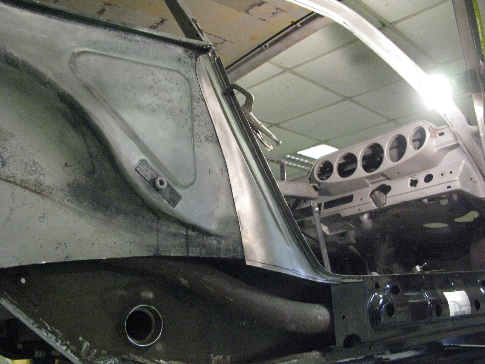
LH Rear Inner Wing: B-post Area Repair

Another area where previous action had taken its toll. As I mentioned the car had been widebody-fied then partially reverted, so had already had 3 sets of rear wings including the original factory ones. I think ours will be the fourth set.

Barry says:
The front area of the rear inner wing had suffered through having had at least two B-posts welded to it, and then removed. Additionally there were several areas of corrosion. Replacement of this metal has the advantage that the welding on of the new B-post (rear wing) is much easier going from new to new metal.

Here's what we started with:

So it's another fairly complex repair panel, again allowing us to keep the bulk of the original metal.
Luckily Barry says:

One of my favourite repairs!
He's cheerful today.

I've got some tooling I made up last year for the Pullmax machine, and it makes it very straightforward to produce the pressing in this panel.
There is some tricky shaping to do around this area however, as the inner wing has more curves (in different directions) than might be assumed.
There is a degree of shrinking / stretching that needs to be done in order to allow the panel to lie nicely relaxed on the parent metal, ready for scribing in.

The repair panel fabrication process looks like this:

"Very straightforward", I'm sure we can all agree...

All that remains is to chop out the old bit and bung in the new bit. By now I had mastered the required technical language.

2016 MetalworkRichard Fry
LH Floor Edge

Finishing off the floor edge repair panel, and welding it in. The original floor was mostly very good, so these edges are the only new bits.

With the inner sill cavity all cleaned up and primed, the new floor edge (previously scribed and trimmed) could be prepared whilst the sill area paint was drying.

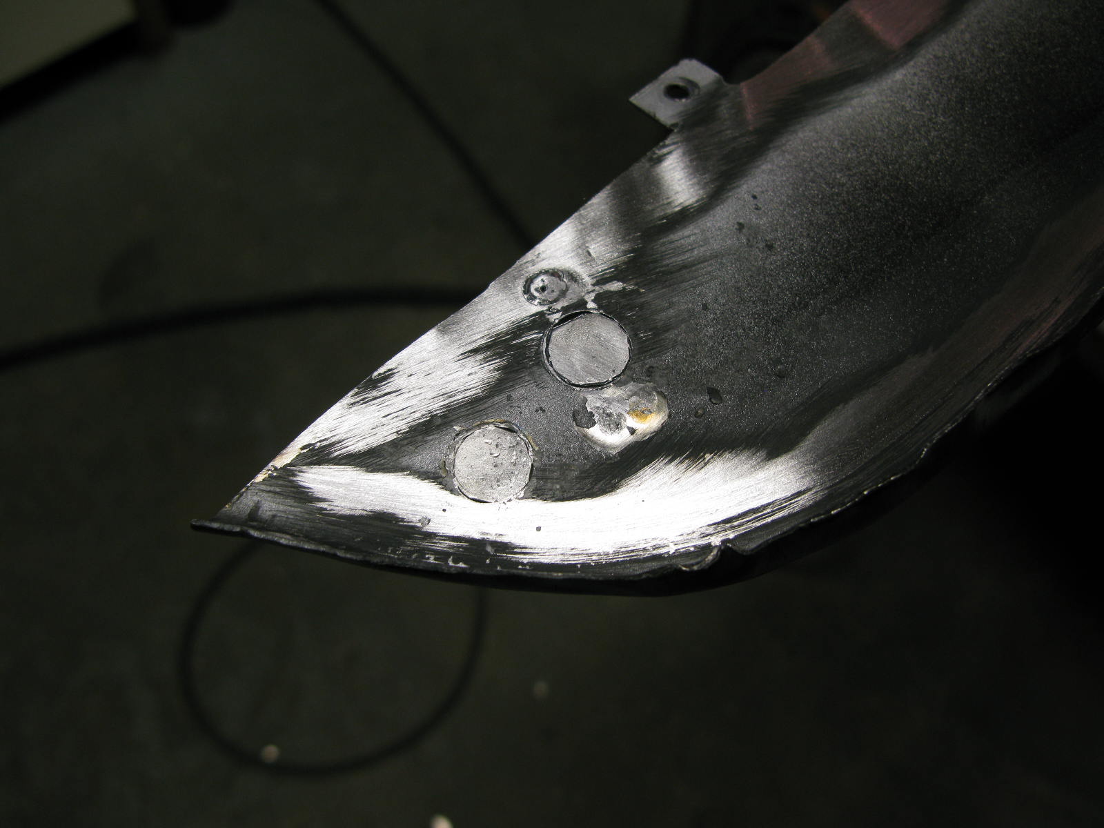
There are all sorts of holes in the floor edge, only two of which we want, and even those are 10mm rather than our 8mm.
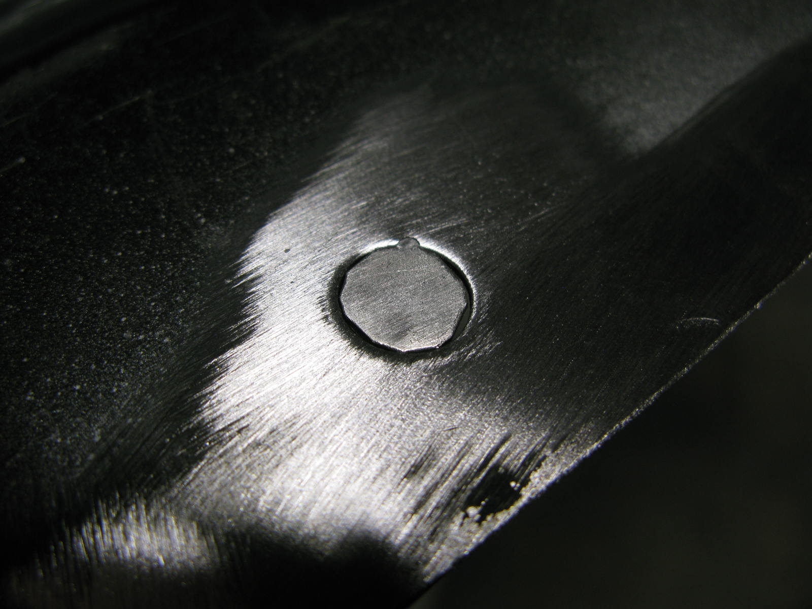
They all get welded up, and then I'll drill some new 8mm's later on. Each hole gets a little custom disk, this gets dropped in and hammer and dollied until it sits in the hole unassisted. The area is welded up, ground back and linished smooth.
This is repeated for each hole.

With the inner sill area dry, the various weld sites are stripped of any etch primer over-spray, and re-primed with Wurth weld-thru zinc-rich primer. At last the floor could be welded in.

2016 MetalworkRichard Fry
Rear Window Flange LH

Both rear window flanges were a mess, presumably because of the previous rear wing replacements in the narrow->wide->narrow history of the car.
Here's the LH one being sorted out:

2016 MetalworkRichard Fry
Top Front of the LH Rear Inner Wing

Including pimple. As Barry explains:

Only point of interest is the little pimple. Made simply with a round chisel knocking the metal into a 13mm socket. So low tech.
There is one trick however, and that's to form the pimple first, and then overlay the cardboard template to get the repair's outline. This ensures the pimple is spot on, position-wise.

2016 MetalworkRichard Fry
LH A-Post Base

As previously mentioned, we decided to keep most of the A-Post bases, so...

The A-post base was just slit off, new flanges added on and after the above, was welded back into place after blasting internally and priming.

The previous repair had skirted around the A-post base, hence the odd 'blending out' at the front on the 'before' picture. Later on, anything that shows here will be run over with the big single sided welder for some cosmetic welds to be added. All the structural welding here has already been dealt with of course.

2016 MetalworkRichard Fry
LH Torque Tube Area: Centre Web Fabrication

Barry's words again:

This area is very tricky to make. Doesn't look much at all, but it's got to accurately fit in several places, one of the hardest being down to the floor, particularly as it curves over the rear of the floor pressing.

I've not got tooling for a 2.2 style inner web, but do have the left hand side for 2.4 and onward (RH pattern to follow soon). As a consequence I used my tooling to roughly fabricate a 2.4 style panel, and then free-hand re-worked it to an approximation of a 2.2.

These pictures show it in 2.4 style, a later sequence shows it properly in place. The 2.2 shell is helpful, in that the heater tube goes over the torque tube, giving many options on shapes to get from the upper area of the inner wed, down to the flange at the base. It gives lots of wiggle room compared to the 2.4, which have none at all.

As it is, it's got to follow the outer edge of the floor, the horizontal inner portion of the floor, the shape of the upper inner web, the torque tube and end up at the right place at the base ready to receive the new rear inner wing repair. There's a lot going on here! The sad thing is, to glance at it, you'd think it was an hour or so of rough bashing to make the thing. Sadder still, it's buried deep within the car, and in all likely hood will never be seen again.

Last two pictures (sort of) show how the panel lies over the rear of the floor and back down to the floor base.

When I used to make this whole area 'freehand' it was nearly two days work to get it all to fit, and that was usually in three pieces. BTW, all of my repairs are made from full 18SWG (1.2mm / nominal 48thou - actually 44thou) steel. It takes some shifting.

2016 MetalworkRichard Fry
LH Floor Edge Etc

Barry says:

As you can see, I have a little floor edge jig which I use if there's no original (trustworthy) metal to use as a guide for establishing the exact position of the floor edge. If this is out, it can tilt the whole outer sill, leaving you problems ahead when it comes to gapping between door and outer sill.

You can also see that the area beneath the torque tube is all stripped out ready to receive a new torque tube end and surrounding sheet metal.

And, just for fun, let's have a look at another old repair... 
held on with hope alone, no welds had penetrated through to the substrate at all.

2016 MetalworkRichard Fry
Base of LH Inner Member

In which we get to see some fabrication of small repair panels. Over to you, Barry:

With the recently replaced floor edge, together with the soon to be replaced A-post base area removed, work could start in tidying up the base of the main inner member (sill, chassis rail? You decide).

As you can see, the previous repairer had attempted to weld individual holes up. Sometimes this is fine if it's one or two isolated holes in otherwise good metal. In this case though, the whole area was replaced. Same principle was used all the way along. In the end, just one repair was retained right at the rear of the run. Not shown in detail, but that thin area near the round hole was replaced at the same time.

2016 MetalworkRichard Fry